Throttle Linkage
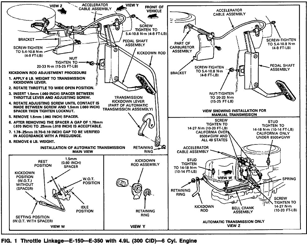
Fig 1
E-150-350 with 4.9L 6 cyl.
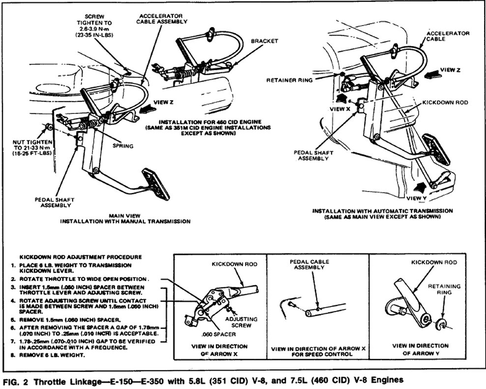
Fig 2
E-150-350 with 5.8L 8 cyl.
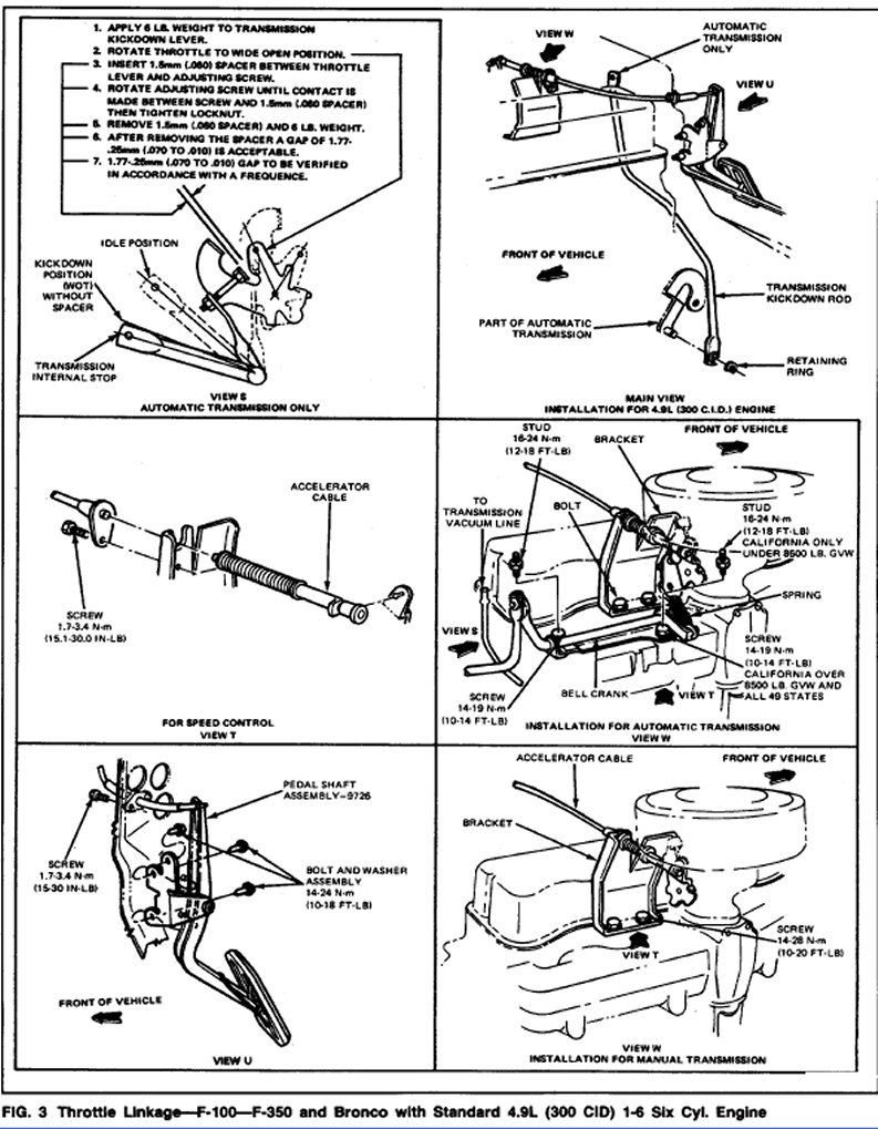
Fig 3
F 100-350 4.9 6 cyl.
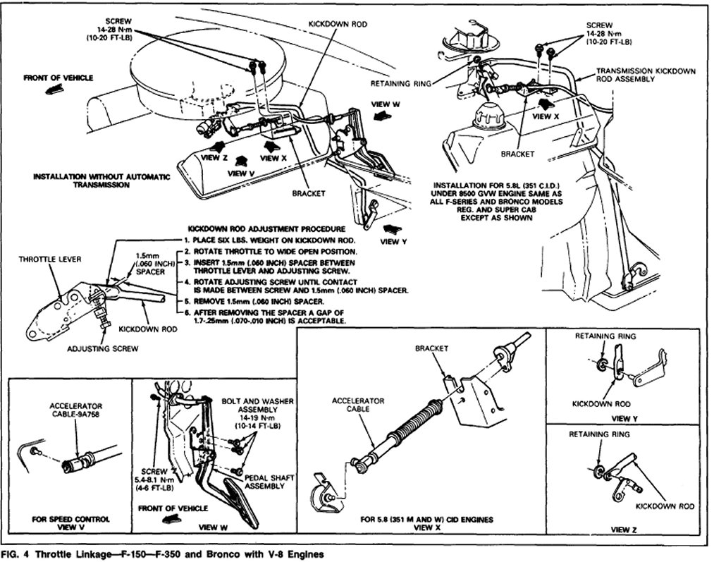
Fig. 4
F 150-350 and Bronco V8
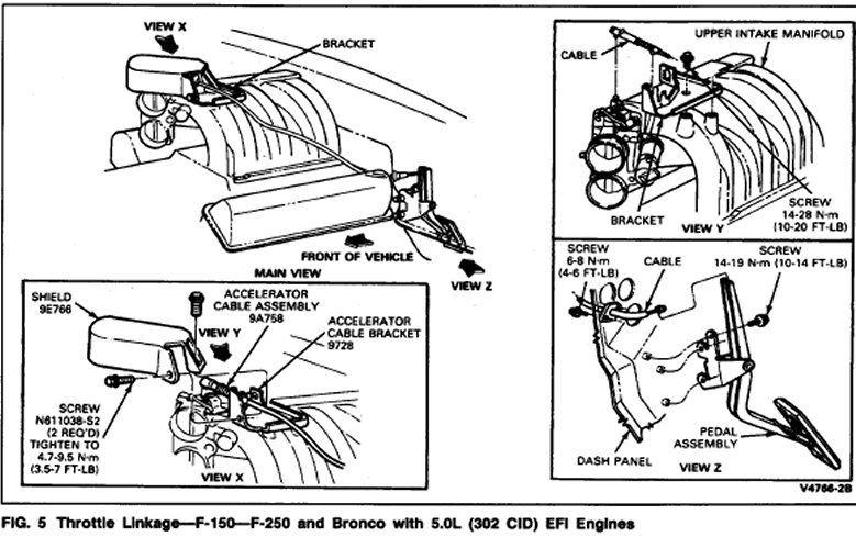
Fig. 5
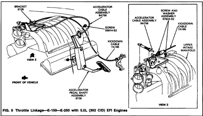
Fig 6
E 150-250 with 5.0L EFI
Non-Automatic Overdrive Transmissions
Instructions for adjusting throttle linkage used on all gasoline-engine trucks are contained in fig. 1 through 5. refer to the appropriate Fig. for procedure.
Whenever possible, the engine should be at operating temperature when throttle linkage adjustments are made.
WARNING: THROTTLE RETURN SPRINGS MUST BE REINSTALLED AS INDICATED IN THE ILLUSTRATIONS AND INSTRUCTIONS IN ORDER TO INSURE PROPER ACCELERATOR RETURN. AFTER ADJUSTMENT CHECK TO INSURE THE ACCELERATOR RETURNS TO IDLE ON SLOW RELEASE OF FOOT PRESSURE, WITHOUT BINDING OR DRAGGING.
Throttle Valve (TV) Control Linkage System Automatic Overdrive Transmission
Refer to adjustments AOD for adjustment procedure. AOD
REMOVAL AND INSTALLATION Except 5.OL EFI Engines
Linkage disconnect points are shown in Figs. 1 through 5. Installation torque specifications of major parts are also given.
Be sure to reinstall throttle return springs in the manner shown on the illustrations.
5.OL EFI Engines Removal
Refer to Figs. 5 and 6.
1. Remove cable from pedal shaft.
2. Remove cable from dash panel.
3. For F-series vehicles, remove the two screws that attach the shield to the accelerator cable bracket. Remove the shield.
4. Remove cable from mounting bracket.
5. Remove cable from ball stud.
6. Remove three screws that attach pedal shaft to dash.
7. Remove two screws that attaches the bracket to intake manifold.
Installation
1. Install two screws that attaches the bracket to intake manifold.
2. Install three screws that attach pedal shaft to dash.
3. Install cable to ball stud.
4. Install cable to mounting bracket.
5. Install two screws that attach cable to dash panel.
6. Install cable to pedal shaft.
7. For F-series vehicles, install two screws which attach the shield to the accelerator cable to bracket.