C-5
ADJUSTMENTS
The only adjustments on the transmission are the bands, line pressure and neutral start switch.
To prevent damage to the transmission and to assure proper adjustment, it is essential that the tools and procedures described below are used whenever adjustments are made.
Intermediate Band Adjustment
1. Clean all the dirt from the band adjusting screw area. Remove and discard the locknut.
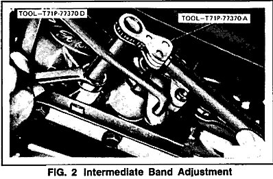
2. Install a new locknut on the adjustment screw.
3. Tighten the adjusting screw using Band Adjusting Ratchet T71P-77370-A and Socket T71P-77370-D or equivalent (Fig. 2). Tool T71P-77370-A or equivalent, is a pre-set torque wrench which will click when the torque on the adjusting screw reaches 13.5 N.m (10 lb-ft).
4. Back off the adjusting screw exactly 4 1/4 turns.
5. Hold the adjusting screw from turning and tighten the locknut to 54 N m (40 lb-ft).
Low Reverse Band Adjustment
1. Clean all the dirt from the band adjusting screw area. Remove and discard the locknut.
2. Install a new locknut on the adjusting screw.
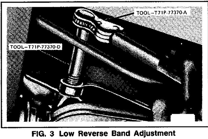
3. Tighten the adjusting screw using Band Adjusting Ratchet T71 P-77370-A and Socket T71 P47370-D or equivalent (Fig. 3). Tool T71 P-77370-A or equivalent, is a pre-set torque wrench which will FIG. 2 Intermediate Band Adjustment click when the torque on the adjusting screw reaches 13.5 N.m (10 lb-ft).
4. Back off the adjusting screw exactly 3 turns.
5. Hold the adjusting screw from turning and tighten locknut to 54 N.m (40 lb-ft).
Line Pressure
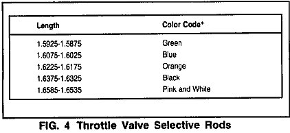
When a replacement vacuum diaphragm is installed, the line pressure must be checked. If the pressure is not to specifications, a longer or shorter throttle valve rod must be installed to bring the pressure within the specified limits. In order to obtain the proper line pressure, five selective rods are available (Fig. 4).
The following procedure will determine if a change in the length of the rod is required.
1. Attach a tachometer to the engine.
2. Attach a hand vacuum pump to the transmission vacuum diaphragm unit.
3. Attach a suitable hydraulic pressure gauge similar to Tool T57L-77820-A or equivalent, to the control pressure outlet on the transmission.
4. Firmly apply the parking brake. On vehicles equipped with a vacuum brake release, apply the service brakes. Otherwise, the parking brake will release when the selector is moved to Drive.
5. Start the engine, allow it to reach normal operating temperature.
6. Set the engine idle speed to the specified RPM.
7. Adjust engine speed to 1000 RPM and apply 10 inches of vacuum to vacuum diaphragm unit. Read and record the control pressure in all selector positions.
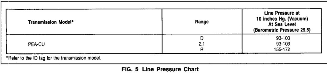
8. Compare the pressure readings from Step 7 to the specified pressure in the line pressure chart (Fig. 5), and proceed as follows:
^ Pressure within specification no change required
^ Pressure below specification use the next longest rod
^ Pressure above specification use the next shortest rod
If the length of the rod is not known, it should be measured with a micrometer.
Neutral Start Switch Adjustment C5 and C6
1. Apply the parking brake.
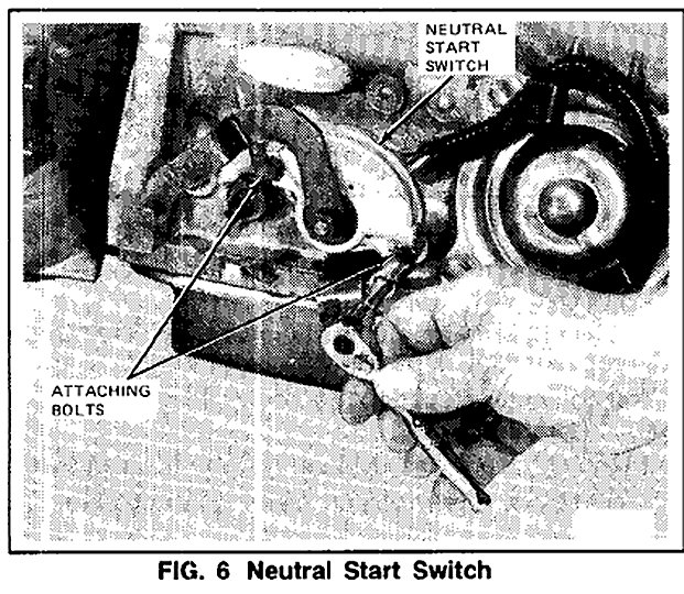
2. With the manual linkage properly adjusted, loosen the two switch attaching bolts (Fig. 6).

3. Place the transmission manual lever in NEUTRAL. Rotate the switch and insert the gauge pin (No.43 drill shank end) into the gauge pin holes of the switch. The gauge pin has to be inserted a full 12.303 mm 31/64 inch into the three holes of the switch (Fig. 7).
4. Tighten the two neutral start switch attaching bolts to 6.5-8.0 N.m (55-75 in-lbs). Remove the gauge pin from the switch.
5. Check the operation of the switch. The backup lamps should operate only with the transmission selector lever in REVERSE. The vehicle should start only with the transmission selector lever in PARK and NEUTRAL.