Control Valve Body
Control Valve Body
Disassembly
The valve body-to-screen gasket should not be cleaned in a degreaser solvent or any type of detergent solution when disassembling the main control. To clean the gasket, wipe it off with a lint-free cloth.
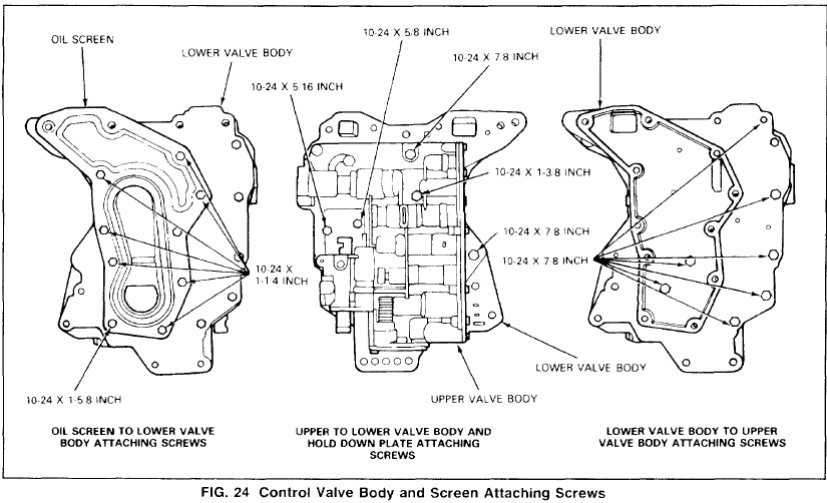
1. Remove the nine screws that attach the screen to the lower valve body (Fig. 24) and remove screen and gasket (Fig. 25).
2. Remove the five upper-to-lower valve body and hold-down plate attaching screws. Remove the seven attaching screws from the underside of the lower valve body (Fig. 24).
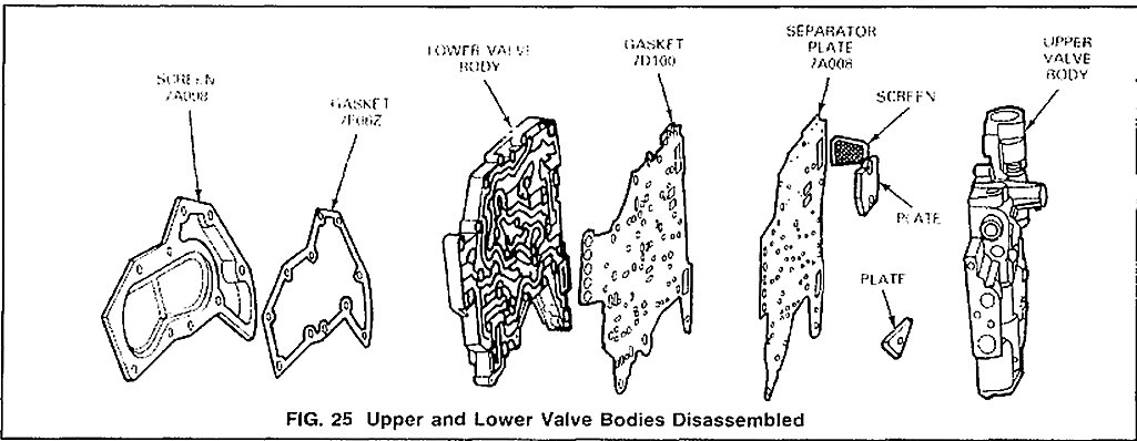
3. Separate the bodies and remove the separator plate and gasket. Be careful not to lose the check valves and springs. Remove and clean the separator plate screen if necessary (Fig. 25).
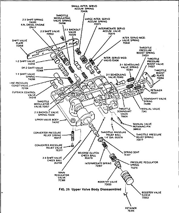
4. Remove the manual valve retaining pin from the upper valve body (Fig. 26).
5. Slide the manual valve (Fig. 26) out of the valve body.
6. Cover the downshift valve bore with a linger, then working from the underside of the body remove the downshift valve retainer. Remove the spring and downshift valve (Fig. 26).
7. Apply hand pressure on the pressure boost valve sleeve end and remove the sleeve retaining clip from the under side of the body. Slowly release hand pressure and remove the sleeve and the pressure boost valve. Remove the two springs, the spring retainer and the main regulator valve from the bore.
8. Apply pressure on the throttle boost valve retaining plate and remove the two attaching screws. Slowly release the pressure and remove plate, throttle pressure boost valve and spring, and the manual low 2-1 scheduling valve and spring from the body (Fig. 26).
9. Apply pressure on the remaining valve retaining plate and remove the eight attaching screws.
10. Hold the valve body so that the plate is facing upward. Slowly release the pressure and remove the plate.
11. Remove the spring and the intermediate servo modulator valve (Fig. 26) from the valve body.
12. Remove the intermediate servo accumulator valve and springs.
13. Remove the 2-3 back out valve and spring
14. Remove the 2-3 shift valve, spring and the throttle modulator valve.
15. Remove the 1-2 shift valve, DR-2 shift valve and the spring from the valve body.
16. Remove the line pressure coasting regulator valve, (Fig. 26) from the body.
17. Remove the cutback control valve to complete the disassembly of the control valve.
Assembly
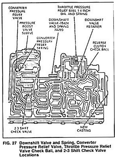
1. Place the downshift valve and spring in the valve body. Compress the spring and install the retainer from the underside of the body (Fig. 27).
2. Place the valve body on a clean surface with the passage side facing up. Place the converter relief valve spring in its bore (Fig. 27). Coat the converter pressure relief valve with petroleum jelly and place it on top of the spring. Place the 2-3 shift valve check ball in its cavity. Place the throttle pressure relief valve spring in its bore (Fig. 27). Coat the throttle pressure relief valve check ball with petroleum jelly and place it on top of the spring.
3. Install the separator screen in the separator plate if it was previously removed. Be sure the screen tabs are flush with the separator plate surface. Carefully position the separator plate and new gasket on the two valve body. Place the two hold down plates on the separator plate and install the attaching screws finger tight.
4. Place the lower body and plate assembly on the upper valve body (Fig. 24) and install the attaching screws finger tight.
5. Install the oil screen screws loosely, without the screen, to properly align the upper and lower valve bodies, gasket and separator plate.
6. Tighten the two bolts that are covered by the screen to 5.0-6.2 N.m (40-55 in.-lbs).
7. Remove the oil screen attaching screws and place the gasket and oil screen in position on the lower valve body. Re-install the screen attaching screws (Fig. 24).
8. Tighten all the valve body and screen attaching screws to 5.0-6.2 N.m (40-55 in.-lbs).
9. Place the cutback control valve (Fig. 27) and the line pressure coasting regulator valve in the valve body.
10. Place the one spring, DR-2 shift valve and the 1-2 shift valve in the body.
11. Place the throttle modulator valve and spring and the 2-3 shift valve in the valve body.
12. Place the spring and the 2-3 backout valve in the valve body.
13. Place the two springs and the intermediate servo accumulator valve in the valve body.
14. Place the intermediate servo modulator valve and spring in the body.
15. Carefully place the valve retaining plate on the body and secure it with the eight attaching screws. Tighten the two hex washer head screws to 2.5-5.0 N.m (20-45 in-lbs). Tighten the remaining six screws to 2.5-4.5 N.m (20-40 in-lbs).
16. Place the throttle pressure boost valve and spring in the valve body. Place. the manual low 2-1 scheduling valve and spring in the valve body and install the retaining plate. Tighten the attaching screws to 2.5-5.0 N m (20-45 in.-lbs).
17. Place the spring retainer on the stem of the main regulator valve so that the retainer flange is next to the valve shoulder. Place the main regulator valve, spring retainer, two springs, pressure boost valve and sleeve in the bore Apply hand pressure on the end of the pressure boost valve sleeve and install the spring clip retainer in the groove on the under side of the body so that the clip is inserted into the end groove in the sleeve Be sure that the pressure boost valve sleeve is free in its bore.
18. Place the manual valve in the valve body and install the retaining pin in the body.
4. Place the lower body and plate assembly on the upper valve body (Fig. 25) and install the attaching screws finger tight.
5. Install the oil screen screws loosely, without the screen, to properly align the upper and lower valve bodies, gasket and separator plate.
6. Tighten the two bolts that are covered by the screen to 5.0-6.2 N m (40-55 in.-lbs).
7. Remove the oil screen attaching screws and place the gasket and oil screen in position on the lower valve body. Re-install the screen attaching screws (Fig. 25).
8. Tighten all the valve body and screen attaching screws to 5.0-6.2 N.m (40-55 in.-lbs).
9. Place the cutback control valve (Fig. 27) and the line pressure coasting regulator valve in the valve body.
10. Place the one spring, DR-2 shift valve and the 1-2 shift valve in the body.
11. Place the throttle modulator valve and spring and the 2-3 shift valve in the valve body.
12. Place the spring and the 2-3 backout valve in the valve body.
13. Place the two springs and the intermediate servo accumulator valve in the valve body.
14. Place the intermediate servo modulator valve and spring in the body.
15. Carefully place the valve retaining plate on the body and secure it with the eight attaching screws. Tighten the two hex washer head screws to 2.5-5.0 N.m (20-45 in-lbs) Tighten the remaining six screws to 2.5-4.5 N m (20-40 in-lbs).
16. Place the throttle pressure boost valve and spring in the valve body. Place. the manual low 2-1 scheduling valve and spring in the valve body and install the retaining plate. Tighten the attaching screws to 2.5-5.0 N.m (20-45 in.-lbs).
17. Place the spring retainer on the stem of the main regulator valve so that the retainer flange is next to the valve shoulder. Place the main regulator valve, spring retainer, two springs, pressure boost valve.