Disassembly
Disassembly and Assembly
NOTE: Before beginning the transmission overhaul review the following guidelines These general rules are provided to emphasize the need for attention to detail and care when servicing an automatic transmission
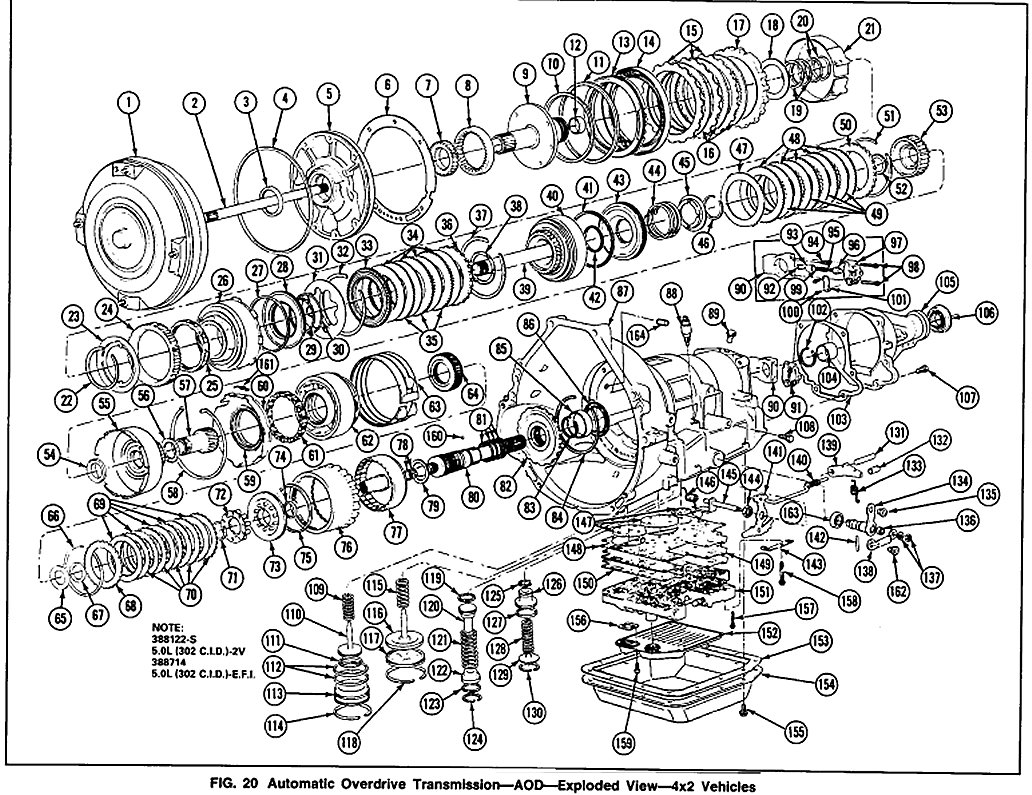
Fig. 20
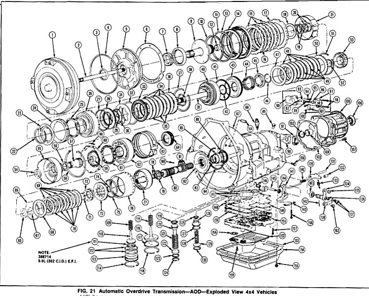
Fig. 21
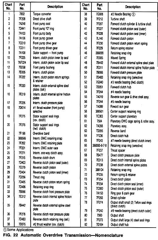

Fig. 22 Charts
It is important to completely clean all transmission components, including converter, cooler, cooler lines, main control valve body, governor, all clutches, and all check balls after any transmission servicing that generates contamination. These contaminants are a major cause for recurring transmission troubles and must be removed from the system before the transmission is put beck into service.
In addition, the cleaning of debris from the direct clutch check ball is often omitted. This omission can lead to a repeat servicing of the transmission.
1. Cleaning and flushing procedures for transmission components, including the direct clutch check ball.
2. Thorough cleaning of the transmission exterior will reduce the possibility that damaging contaminants might enter the subassemblies during disassembly and assembly.
3. All fasteners must be tightened to the torque indicated in the specifications at the end of this Section. Specifications
4. When building-up sub-assemblies each component part should be lubricated with clean transmission fluid. It is also good practice to lubricate the sub- assemblies as they are installed in the case.
5. Needle bearings, thrust washers and seals should be lightly coated with petroleum jelly during subassembly build-up or transmission assembly.
6. Many components and surfaces in the transmission are precision machined. Careful handling during disassembly, cleaning, inspection and assembly can prevent unnecessary damage to machined surfaces.
7. When building-up sub-assemblies or assembling the transmission always use new gaskets and seals.
8. The transmission repair area should be kept clean, well organized and supplied with clean lint-free shop cloths.
9. Whenever a seal is removed from a piston, shaft or servo, note the type of seal and when applicable, the direction of the sealing lip.
10. Always use the specified transmission fluid when rubricating seals or other components prior to assembly (refer to Specifications for the proper fluid). Specifications
NOTE: Do not soak oil filter in a solvent cleaner. The filter element could disintegrate. Replace the filter when necessary.
Transmission
Disassembly
Refer to Figs. 20, 21 and 22.
1. Mount the transmission in holding fixture, Tool T57L5O0-B or equivalent.
NOTE: Before removing any of the subassemblies, thoroughly clean the outside of the transmission to prevent dirt from entering the mechanical parts.
During the repair of the subassemblies, certain general instructions which apply to all units of the transmission must be followed. These instructions are given here to avoid unnecessary repetition.
Handle all transmission parts carefully to avoid nicking or burring the bearing or mating surfaces.
Lubricate all internal parts of the transmission with transmission fluid before assembly. DO NOT USE ANY OTHER LUBRICANTS EXCEPT ON GASKETS AND THRUST WASHERS WHICH MAY BE COATED WITH PETROLEUM JELLY TO FACILITATE ASSEMBLY. ALWAYS INSTALL NEW GASKETS WHEN ASSEMBLING PARTS OF THE TRANSMISSIONS.
Tighten all bolts and screws to the recommended torque as listed on Specifications in this Section. Specifications
2. Remove the torque converter by grasping firmly and pulling straight out of the transmission.
3. Remove the 14 oil pan attaching bolts, the oil pan and the pan gasket. Discard the gasket.
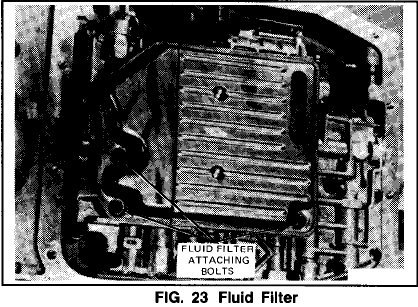
4. Remove the three fluid filter attaching bolts (Fig. 23). Remove the filter grommet and gasket. Discard the gasket.
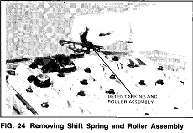
5. Remove the shift linkage detent spring and roller assembly (Fig. 24).
6. Remove the remaining (25) valve body-to-case attaching bolts, the valve body assembly and the valve body gasket.
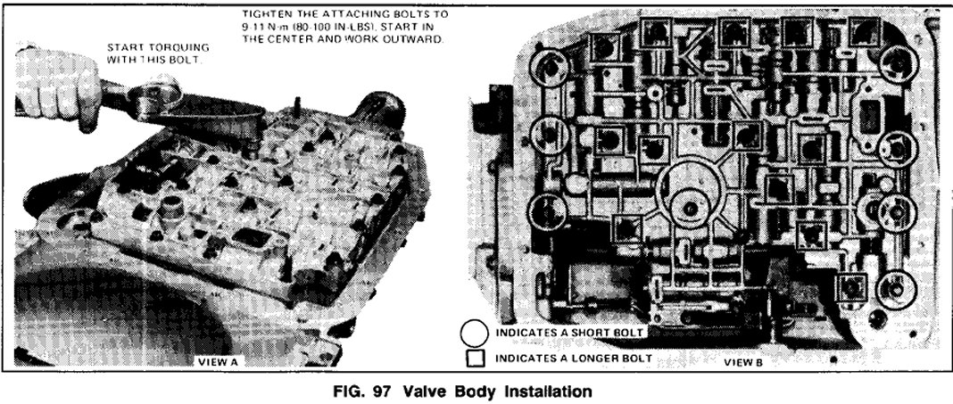
NOTE: The (4) front, (1) center and (3) rear attaching bolts are shorter than the others as indicated by a circle (Fig. 97).
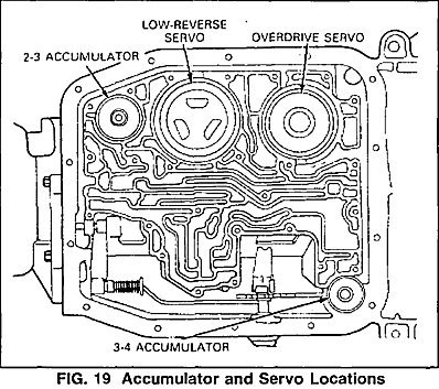
Fig. 19
7. Push down on the 3-4 accumulator cover (Fig. 19) and remove the retaining ring using a thin-bladed screwdriver.
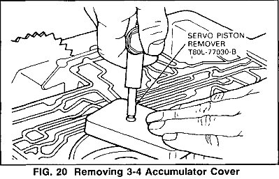
8. Remove the 3-4 accumulator cover. If the cover sticks in the bore, use Servo Piston Remover, T8OL-77030-B (or equivalent) and air pressure to aid removal (Fig. 20).
CAUTION: Make certain a portion of Servo Piston Remover T8OL-77030-B (or equivalent) extends over the bore to prevent the cover from flying out of the bore.
9. Remove the 3-4 accumulator piston.
The piston uses a scarf-cut teflon seal and comes out with very little resistance.
NOTE: Some models may use a spring. The piston and spring may be different from that shown.
10. Using a wide-bladed screwdriver or wooden dowel, push down on the 2-3 accumulator cover and remove the retaining ring (Fig. 19).
11. Remove the 2-3 accumulator cover and the piston spring.
12. Remove the 2-3 accumulator piston. The piston uses two scarf-cut teflon seals and comes out with very little resistance.
13. Using a hammer handle or wooden dowel, push down on the low-reverse servo cover and remove the snap ring (Fig. 19).
14. Remove the low-reverse servo cover, servo piston and the piston return spring. If necessary, a magnet can be used to lift the piston from the bore.
15. Using a hammer handle or wooden dowel, push down on the over-drive servo cover and remove the snap ring (Fig. 19).
16. Remove the overdrive servo cover and piston as a unit. If the cover sticks in the bore, use Servo Piston Remover T8OL-77030-B (or equivalent) and air pressure to aid removal (Fig. 20). Remove spring.
CAUTION: Make certain a portion of Servo Piston Remover T8OL-77O3-B (or equivalent) extends over the bore to prevent the cover from flying out of the bore.
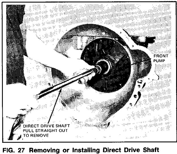
17. Remove the direct drive shaft (Fig. 27).
18. Remove the (7) pump body attaching bolts.
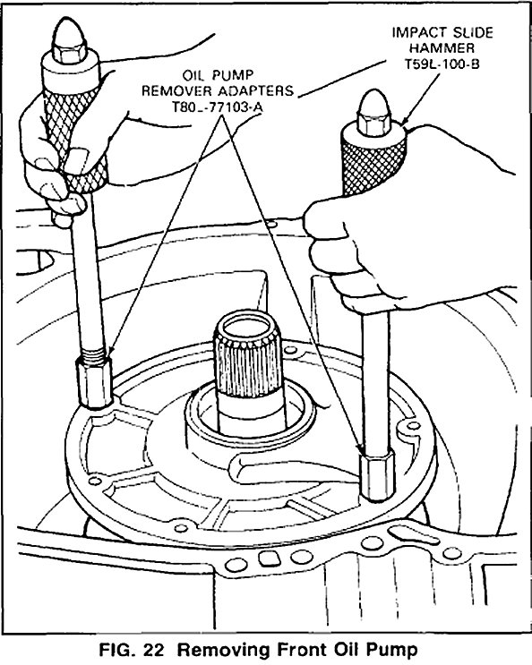
19. Remove the pump assembly using Slide Hammers 159L-100-B and oil pump remover Adapters T8OL-77103-A as shown in Fig. 22.
20. Remove the pump-to-case gasket.
Fig. 20
Fig. 21
Fig. 22 Charts
21. Grasp the turbine shaft firmly and pull these components (Refer to Fig. 20 and 21) out of the case as an assembly:
a. Intermediate clutch pack
b. Intermediate one-way clutch
c. Reverse clutch
d. Forward clutch
Use care not to damage the overdrive band friction liner material with the Reverse clutch drive lugs.
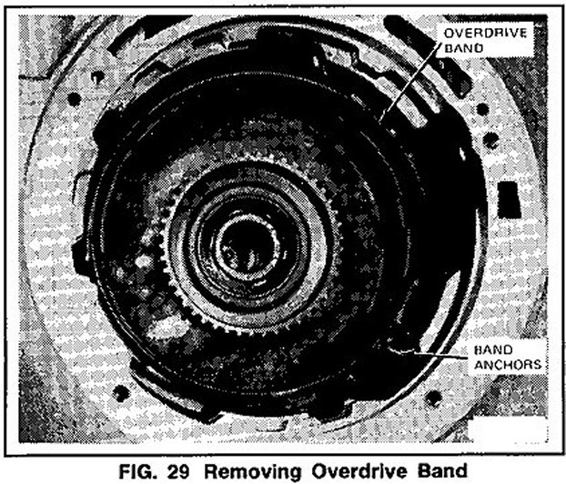
22. Disengage the overdrive band from the anchor pins and remove from the case (Fig. 29).
23. Remove the forward clutch hub and the No.3 needle bearing as an assembly.
24. Remove the forward sun gear, theNo.5 needle bearing, the reverse sun gear and drive shell and the No.4 needle bearing as an assembly.
25. Remove the center support snap ring. Note position of tabs for assembly.
26. Using a screwdriver, pry the anticlunk spring out from between the center support and the case. Note: the location for assembly.
27. Remove the center support and planetary carrier as an assembly.
28. Remove the reverse band.
29. if the direct clutch hub did not come out with the planetary carrier, reach in and lift it out of the direct clutch.
30. Remove the (6) extension housing attaching bolts and the extension housing. Remove and discard the extension housing gasket.
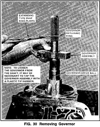
31. Remove the retaining ring and governor assembly (Fig. 30).
NOTE: If the transmission is positioned with the output shall pointing up, do not allow the shalt assembly to fall through the case when the governor is removed.
32. Remove the governor drive ball from the output shaft. A magnet may be used to aid removal.
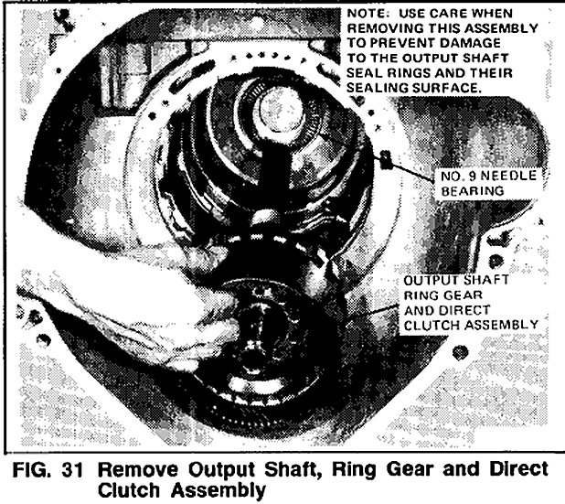
33. Remove the output shaft, the ring gear and the direct clutch as an assembly, through the front of the case (Fig. 31).
34. Remove the output shaft No.9 needle bearing from the rear of the case.
35. Remove the intermediate one-way clutch.
36. Remove the reverse clutch assembly from the forward clutch assembly.