Pump and Intermediate Clutch Assembly
Pump and Intermediate Clutch Piston
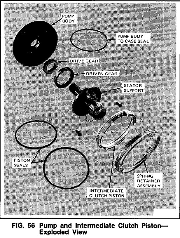
Refer to Fig. 56.
Disassembly
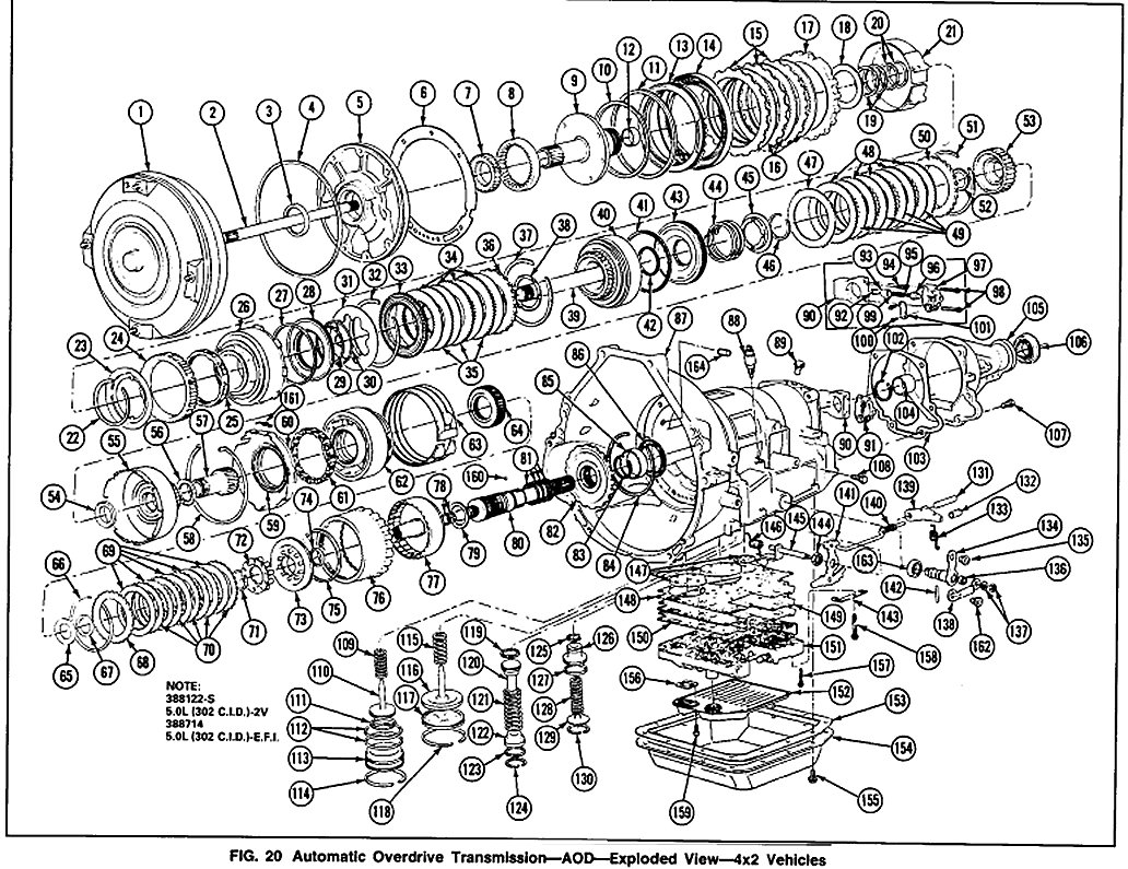
Fig. 20
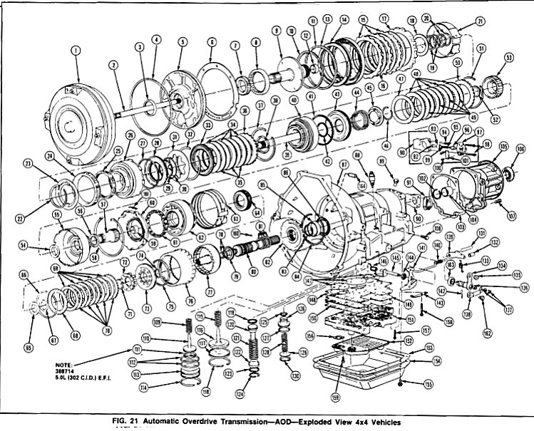
Fig. 21
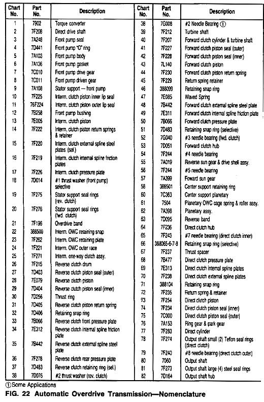

Fig. 22 Charts
1. Remove the No.1 thrust washer (Figs. 20 and 21).
2. Remove the four pump seal rings (Figs. 20 and 21). The reverse clutch rings are larger than the forward clutch rings.
3. Remove the pump body-to-case seal and discard.
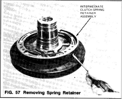
4. Remove the spring retainer assembly by carefully dislodging the tabs (Fig. 57)
5. Remove the intermediate clutch piston.
6. Remove the five stator support bolts (1Omm) and the stator support.
7. Remove the drive and driven pump gears from the pump body.
Assembly
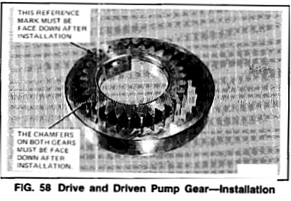
1. Install the drive and driven pump gears in the pump body as shown in Fig. 58. Chamfers on both gears face into the pump body.
2. Position the stator support and install the bolts. Tighten bolts to 16-22 N.m (12-16 ft-lbs).
3. Install a new pump to case seal.
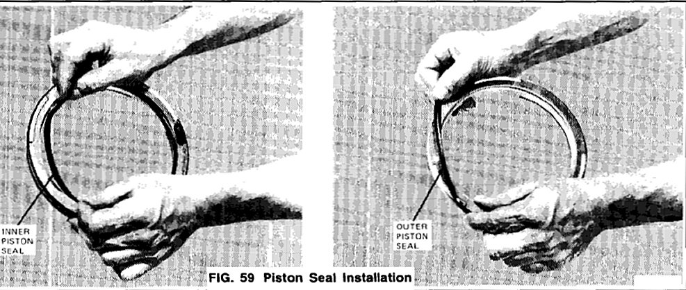
4. Install new seals on the clutch piston. Note the direction of the sealing lip before installation. The lips point away from the spring posts (Fig. 59).
5. Install the clutch piston as follows:
a. Coat the piston seals and the pump body sealing area with petroleum jelly.
b. lnstall the piston in Seal Protector T80L77005-A (or equivalent).
c. Install the piston in the pump body and push to the bottom of the bore by exerting even thumb pressure on the piston.
IMPORTANT NOTE: The piston bleed hole must be located at 12:00 position (toward top of transmission).
6. Snap the spring retainer assembly into place on the pump body. Use even pressure.
7. Install the pump seal rings.