Part 2
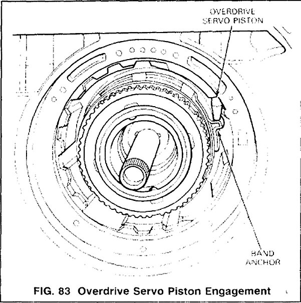
17. With the overdrive servo installed, inspect the piston and band for proper position and engagement. If the band anchor and piston are not properly engaged as shown in Fig. 83, remove the servo and reposition the band as necessary.
18. Install the intermediate clutch pack components in the following order.
1. The pressure plate
2. The clutch pack
3. The selective steel plate
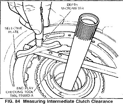
19. Measure the intermediate clutch clearance using a depth micrometer and end-play checking Tool T8OL-77003-A (Fig. 84). Set the end-play tool across the pump case mounting. Locate the micrometer end-play bar and read depth. The depth at the intermediate clutch separator plate should be 41.5-41.8mm (1.634-1.646 inch) for the 4.9L (300 CID) and 5.OL (302 CID) EFI applications. Check depth again 180 degrees opposite and assure the average depth is within tolerance.
NOTE: Maintain a downward pressure on the clutch pack while measuring depth.
If the depth is not within tolerance, the following size selective steel separator plates are available:
0.071inch--0.067 inch
0.081inch--O.077 inch
0.091inch--0.087 inch
0.101inch--O.097 inch
Install the correct plate and recheck the clearance.
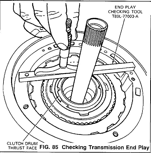
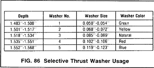
20. Check transmission end-play by locating the depth micrometer on end-play Bar T8OL-77003-A so that depth is measured at the reverse clutch drum thrust face (Fig. 85). Check end-play 180 degrees opposite to determine average depth. The following chart shows the proper selective thrust washer for various depth measurements (Fig. 86).
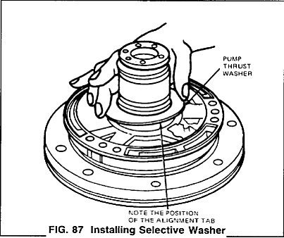
21. Install the selective washer determined in Step 20 on the Pump as shown in Fig. 87. Use petroleum jelly to hold it in place.
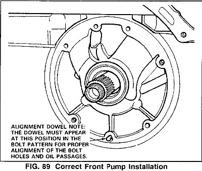
22. lnstall a pump alignment dowel. The alignment dowel can be fabricated by removing the head from a M8-1.25 bolt. Install the dowel only a few threads in the position shown in Fig. 89.
23. Install a new pump gasket.
24. Using Slide Hammers T59L1OO-B and metric Adaptors T8OL-77103-A (or equivalent), lower the pump assembly into the case to the position shown in Fig. 89.
25. Remove the alignment dowel and install the seven pump attaching bolts. Alternately tighten the bolts a few turns at a time to draw the pump into the case. Tighten the attaching bolts to the specified torque. Specifications
26. Assemble 3-4 accumulator. Install the piston (and spring, if so equipped). Lubricate the rubber seal on the cover and the top of the bore to help cover installation. Install the cover.
IMPORTANT NOTE: After assembly, the cover must be fully up and seated against retaining ring to avoid exposing a pressure passage. Use air pressure if necessary to seat cover up against retaining ring.
27. Assemble the 2-3 accumulator.
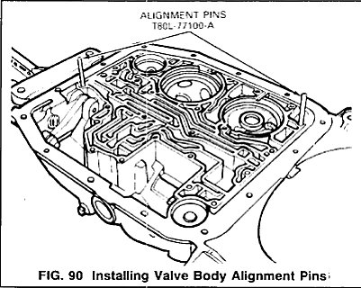
28. Install valve body alignment Pins T8OL-77100-A (or equivalent) in the positions shown (Fig. 90).
29. Install the valve body gasket and the valve body assembly over the pins.
NOTE: Make sure the manual and throttle levers are properly positioned before installing the valve body attaching bolts.
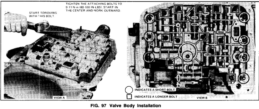
30. Loosely install (25) valve body attaching bolts. Starting at the center and working outward, tighten the bolts to specification (8mm socket) (Fig. 97, View A).
NOTE: Two different length bolts are used. The shorter bolts are used at the four front, one center and three rear locations. See picture (Fig. 97, View B).
31. Remove the alignment pins and install bolts (short). Install the detent spring and roller assembly (long bolt). Tighten the bolts to 9-11 N.m (80-100 in-lbs) torque.
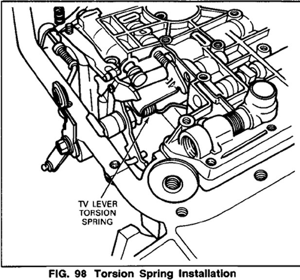
32 Position the TV lever torsion spring against the separator plate V notch (Fig. 98). This spring pushes the throttle lever in the direction of wide open throttle.
33. Install the filter grommet, a new filter gasket and the filter on the valve body.
NOTE: If the fluid was contaminated be sure to use a new filter. Never attempt to clean or reuse a dirty filter.
34. Install the filter attaching bolts (8mm) and tighten to 9-14 N.m (80-120 in-lb) torque.
35. Position a new pan gasket and install the oil pan (1Omm socket. Tighten the attaching bolts to the specified torque.
36. Position a new gasket and install the extension housing. Tighten the attaching bolts to the specified torque. Specifications
37. Install the direct driveshaft.
38. Install the torque converter. Make sure the converter is fully seated in the pump.